10. Seat belt installation checks
Seat belt installation rules and inspection for vehicles fitted with more than 8 passenger seats and first used before 1 October 2001.
Vehicles fitted with more than 8 passenger seats and first used before 1 October 2001 may be subject to a seat belt installation check.
This can only be carried out by full Class 5 authorised test stations. It is essential therefore that you correctly identify vehicles that require a seat belt installation check.
A vehicle will require a seat belt installation check if it has more than (both of the following):
- 8 passenger seats fitted (see note below)
- legally required number of seat belts fitted (see Appendix C)
and one of the following:
- there is no proof that all the seat belt anchorage points have been type approved (see below)
- there is no proof that a seat belt installation check has been previously carried out (this will be by a previous VT 20 being produced at time of test showing that the vehicle has had an installation check)
- extra seat belts have been fitted since a previous MOT installation check (Compare the number of seat belts now fitted with the number shown on the last MOT certificate)
Note: If it is obvious that the vehicle is capable of carrying more than 8 seated passengers (for example, by having wheelchair tracking/clamps fitted) the presenter of the vehicle should be asked how many passengers the vehicle carries in normal use to establish the seating capacity.
For vehicles first used before 1 October 2001 to be exempt from the check, they must have been fitted with a type approved seat belt installation by the vehicle manufacturer when new.
If you are aware that any of the following vehicles have had any seats/seat belts fitted by any other installer, such as where it has been adapted to carry wheelchairs and has removable seats on tracking, it will not be exempt and will require an installation check.
Type approved seat belt installations can be identified as follows:
Ford Transits:
- 12 and 15 seat (including the driver) Transits manufactured after 1 October 1991 where the fourth character of the VIN Number is ‘E’
- 17 seat (including the driver) Transits where there is a six-figure code EJACL or EJJCL marked in the top right hand of the manufacture’s plate (in the type code box) - in the code the fourth digit marked * can be any character
Land Rover Defender 110 Station Wagon:
- manufactured 1990 - from chassis number 455758
- manufactured 1991 onwards - all chassis numbers
LDV 200 series:
- chassis number from 933478 onwards and the seventh character of the VIN number is ‘S’
LDV 400 series:
- chassis number from 933478 onwards and the seventh character of the VIN number is ‘S’ or ‘V’
LDV Pilot and Convoy:
- chassis number from 000001 onwards and the seventh character of the VIN number is ‘S’ or ‘X’
Mellor bodied Renault Master:
- on production of a PSV certificate of conformity (PSV 408)
All belts should be checked for:
- installation
- operation
- wear
However, the following types of belts should be checked for operation and wear only:
- seat belts for rear or side facing seats
- disabled person’s belts which are permanently attached to the vehicle
- child restraints which are permanently attached to the vehicle
- mandatory seat belts as specified in Appendix C of this manual
If the disabled person’s belts or child restraints are not permanently attached to the vehicle, they do not need to be tested.
Before inspecting the seat belt installation, ask the vehicle presenter to remove seat cushions and to open any access flap or luggage locker door that have been designed to be opened, so that the seat belt installation can be seen.
If some of the parts of seat belt installation are difficult to see, it may help to put the vehicle on a pit or hoist.
The vehicle presenter should show documentary evidence, if available, showing that a seat belt complies with type approval standards but has not been fully type approved, or that is traceable to an installation that has been tested and shown to meet the requirements of ECE Regulation 14 or Community Directive 76/115.
The document should show:
- registration number or chassis number of the vehicle
- name of the installer
- address of the installer
- reference number of the installation test
- date of the installation test
- location of the installation test
Only the original certificates are accepted, meaning photocopies of the certificates will not be accepted. Presentation of the certificate does not replace the need for the examination, but it may support the quality of the installation. It may also help resolve differences over the acceptability of the installation, for example in cases where reinforcement plates have been used.
Diagram 1. Typical methods of attaching seat belts
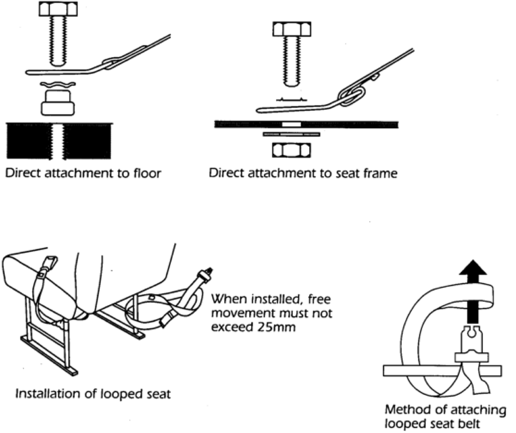
A. Check that the buckle operates correctly on all belts and the seat belt adjusts satisfactorily. Subsequent cutting or reworking of the webbing will be a reason for failure. You can pass the installation if the free end of looped belts or static belts have the webbing folded and stitched to prevent the buckle from being dismantled. You must fail it if there are any knots in the belt webbing.
B. Seat squabs should be removed, so that the condition of the belt and mountings can be inspected. The seat squabs should be put back by the end of the test.
C. Check for any sharp edges that the belt could rub on or pull across during use.
D. Seat belts (other than looped belts) that are anchored to the seat frame or the vehicle floor must be secured with appropriate mounting bolts:
Table 1. Minimum acceptable size and bolt grade for seat belt anchorage
| Type of anchorage | Minibus | Coach or large bus |
|---|---|---|
| single anchorage | M10 standard material | M8 high tensile steel M10 standard material |
| double anchorage | 7/16” standard material M10 high tensile steel |
7/16” standard material M10 high tensile steel |
E. The bolt grade can be identified by markings on the bolt head: * standard material = P, 4.6 or SAE equivalent * high tensile steel = S, 8.8 or SAE equivalent * no markings = standard material
If the bolt grade is not clear, you must assume it to be of standard grade. It’s extremely important that a correct size bolt is used in the seat belt anchorage, for example an 8mm bolt should not be used in an 11.5mm diameter hole. The only exception to this is if a ‘stepped washer’ or a collar is used to eliminate an excessive clearance, and a suitable washer is fitted between the bolt head and the anchorage to prevent the bolt pulling through. You must fail the installation if smaller bolts, self-tapping screws or wood screws have been used.
F. It’s not acceptable to drill tubular seat frames to allow belts to be bolted to the frame. However, if the manufacturer has approved the installation the vehicle presenter must show original documentary evidence by the manufacturer or their agent declaring that the installation is satisfactory.
G. Installation with clamp type brackets can be passed as long as the brackets are properly secured.
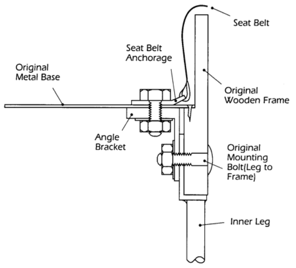
H. Seats with a wooden frame that have the belts mounted directly to the frame, or to a metal base that is attached to the frame by wood screws only, must be rejected. The installation cannot be passed unless there are additional reinforcements that provide a direct load path to the seat and leg and side mounting. These reinforcements could be steel angle sections or plates, but alternative materials may be used as long as they are of comparable strength (see Diagrams 3 and 4 for details of a typical installation).
Diagram 3. Duple dominant seat arrangement - rear view
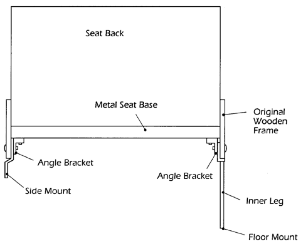
Diagram 4. Duple dominant seat arrangement - sectional view of the reinforcement enlargement
I. Seat belts that are attached to thin sheet metal frames, must have bolts of the minimum dimensions (see Table 1 above) anchoring the belt and be supported by load spreading washers between the frame and the nut. Typically, this would be 25mm in diameter and 2mm thick. If 2 belts are attached at the same point with a single bolt, then a larger reinforcement plate 35mm diameter × 3mm thick (or a rectangular plate of minimum dimensions 21×46×3mm) must be used. The sizes quoted are for steel reinforcement plates, alternative materials may be used but must provide comparable strength.
J. Seat belts fitted to the seats should not be anchored solely to the thin metal sheet separating the boot area from the passenger compartment. Seat belt anchorages should be secured to a strong cross member connected to the structural members of the vehicle. The connection should be able to transfer the seat belt loads into the structure of the vehicle. It may be necessary to construct an additional framework at the rear of the vehicle. An example of a typical reinforcement would be the use of additional square section tubing 40×40×3mm, or angle plate 50×50×4mm across the full width of the vehicle. The quoted sizes are for steel reinforcement. Alternative materials may be used as long as they provide comparable strength. A full width reinforcement that’s only attached to the thin metal sheet is a reason for failure.
K. Three-point belts will only be accepted if:
- the seat has tubular frames or tubular ‘H’ pattern legs, and one of the following is true:
- the seats have been reinforced (see point I above)
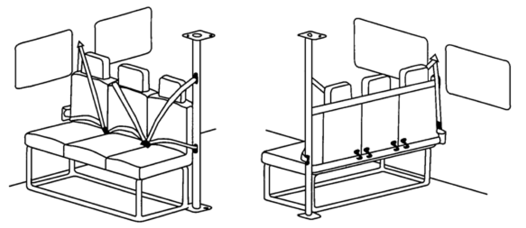
- the vehicle is fitted with a purpose built structure to which the belts are attached (see Diagram 5)
- the belts are attached to solid bodywork
- purpose made seats designed with integral three-point belts as standard have been fitted
Diagram 5. Purpose built structure
L. If seats with tubular frames or tubular ‘H’ pattern legs have lap belts or three-point belts integral to the seat, the seats must be reinforced. Such reinforcements include welded metal buttresses, of similar thickness material as the foot, between the foot and the leg (see Diagram 6), and a welded diagonal brace, either in compression or tension, between the foot and the seat base attachment of each leg.
Diagram 6. ‘H’ pattern legs and their reinforcements
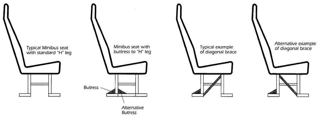
Alternatively, the vehicle presenter can show documentary evidence that the installation complies with the Directive 76/115 or ECE Regulation 14. On quick release seats where the feet are mounted directly to tracking by a coupling, it may not be practical to weld a buttress to the leg or a diagonal brace to the foot due to the presence of the coupling (see Diagram 7). The coupling would prevent any reinforcement being placed in an effective position and the coupling could be damaged by any welding close to it. On this type of installation, the belts can be attached directly to the tracking with quick release mounts or the legs should be modified to use an alternative method of attachment to the tracking.
Diagram 7. Example of quick release seats
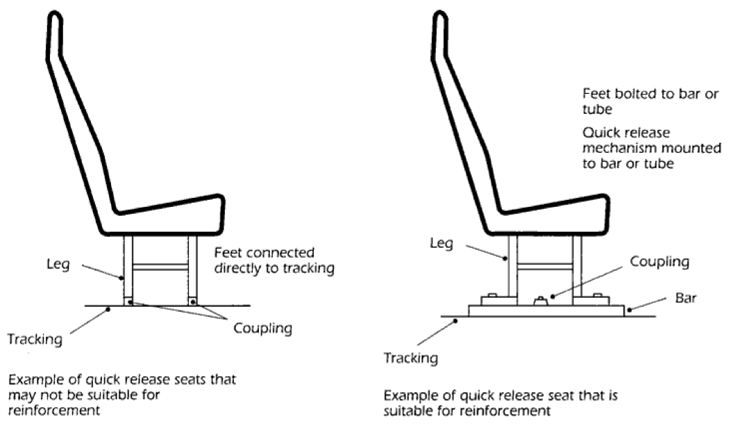
On seats where the feet are mounted to a metal bar or tube that’s connected to tracking with a quick release coupling, the seat has to be reinforced with buttresses and a diagonal brace as detailed above. On vehicles with floor mounted seat belts where the belt is anchored close to the seat mounting bolt then the rear foot of each leg must be buttressed to the leg.
M. Vehicles with lap belts must have padding or protection on hard surfaces such as grab rails or seat stanchions, if passengers could hit their heads on them. The protection does not need to cover the full length of a seat grab rail, but it but should cover at least 300mm directly in front of each passenger. Padding must be compressible, at least 50mm thick and not compress more than 25mm under reasonable thumb pressure. Alternatively, if the padding is 25mm thick, it must not compress more than 5mm. Ordinary seat foam or pipe lagging is unlikely to be dense enough.
N. If the belts are attached directly to a metal floor, a load spreading washer must be used between the nut and the floor. The bolt sizes must be as specified in point D above. Typically, this would be 25mm in diameter and 2mm thick. If 2 belts are attached to the same point with a single bolt, then a larger reinforcement plate that is at least 35mm in diameter and 3mm thick, or a rectangular plate that is at least 21×46×3mm, must be used. The quoted dimensions are for steel reinforcement plates, but alternative materials may be used as long as they are of comparable strength. Reinforcement plates should follow, as far as practicable, any contours in the floor to which they are attached.
O. If a belt is attached directly to a wooden floor, each anchorage must be reinforced with a plate that is at least 35mm in diameter and 3mm thick or a rectangular plate that is at least 21×46×3mm. If 2 belts are attached at the same point with a single bolt, the reinforcement plate must be at least 92mm in diameter and 3mm thick, or a rectangular plate that is at least 65×100×3mm. If 2 belts are attached close to each other, 1 reinforcement plate that is at least 92mm in diameter and 3mm thick or a rectangular plate that is at least 65×100×3mm, should be used. This is to make sure that the bolt holes are not too close to the plate edge. Alternatively, 2 steel reinforcement plates may be used as long as they are at least 52mm in diameter and 3mm thick, or rectangular plates that are at least 46×46×3mm. The quoted sizes are for steel reinforcement plates, but alternative materials may be used as long as they are of comparable strength. Reinforcement plates should follow, as far as practicable, any contours in the floor to which they are attached.
P. Lower anchorages should be at least 320mm apart. This does not need to be the distance between the anchorage points of the belt but it can be between two structural parts of the seat that the belt is routed round. If the measurement is between mounting bolts it should be measured between the bolt centres. You should check that when the belt takes a load, it will not lift or significantly compress the seat cushion. A small amount of compression is acceptable. If mounting rails - designed for the adjustment of seat pitch - are fitted and they use an angled claw type clamp (see Diagram 8) with a clamping face of less than 15mm wide, a seat on which a belt is mounted cannot only be clamped to the rail.
Diagram 8. Typical angled claw fitting
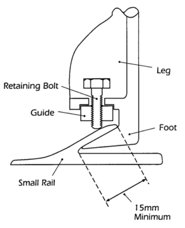
The clamp to the rear foot of each leg must be modified by fitting a bolt through each claw fitting. The bolt must clamp the rear foot of each leg to the rail, floor and a suitable structural member (as in most vehicles). The bolts must have appropriately sized load spreading washers fitted beneath the bolt head and underneath the retaining nut. A single bolt should be at least 8mm (5/16”) in diameter. Any alternative to this is only acceptable if documentary evidence is provided.
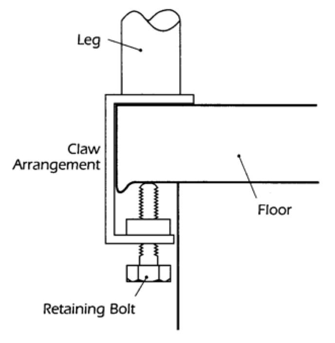
Q. Parallel type claw fittings, for a seat on which a belt is mounted, will be considered satisfactory provided that the securing bolts are fully tightened (see Diagram 9).
Diagram 9. Typical parallel claw fitting
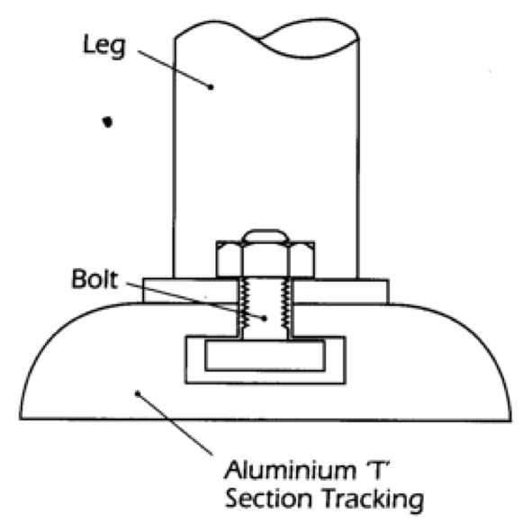
R. If a seat with a mounted belt is bolted to a flat rail, the bolts must pass through the leg, rail, floor and a suitable structural member. Seats can be attached to a purpose built tracking (see Diagram 2) that is designed for securing seats and wheelchairs. The tracking must be securely attached to the vehicle structure with bolts or fasteners in all the retaining holes or marks provided by the manufacturer.
Diagram 2. Typical ‘T’ bolt fitting
Seats with belts should not be fitted directly to wooden floors unless the floors are reinforced with additional steel reinforcement plates. Steel reinforcement plates must be at least 92mm diameter and 3mm thick (or a rectangular plate of at least 65×100×3mm). One of them must be fitted between the underside of the floor and the securing nut below the floor of the rear leg, and the other one must be fitted between the leg and the top side of the floor of the front leg. If the area of the foot of the front leg is larger than 65×100mm, then it’s not necessary to have a front reinforcement plate.
S. A ‘looped’ type seat belt fitting can be used as long as it does not float freely along any part of the seat structure. If the seat belt fitting moves freely more than 25mm, it must be failed.
T. The upper anchorage point should be at least 475mm above the height of an uncompressed seat cushion. This dimension should be measured parallel to the backrest. The upper anchorage point should be at least 110mm from the centre line of the seat back to the side of the seat.
U. A lap belt or the lap section of a three-point belt must be positioned to lie across the wearer’s pelvis and not the stomach. This is to reduce the risk of abdominal injury and to prevent the seat occupant from sliding down and under the lap belt. In practise this may result in the belt lying across the top quarter of the thigh. Seat belt components should not be fitted to seats in such a way that they intrude into the gangway space and passengers are likely to injure themselves by tripping or hitting the component.
| Defect | Category |
|---|---|
| (a) Evidence that original webbing has been cut and/or reworked; eg belts knotted, fraying or fluffing removed/ sealed by burning etc (see note A) | Major |
| (b) Any part of the installation which has a sharp edge which could or is likely to cut or abrade the webbing | Major |
| (c) A directly attached anchorage not secured by standard seat belt mounting bolts and washers as detailed in note D | Major |
| (d) An anchorage insecure | Major |
| (e) A tubular seat frame that has been drilled for the purpose of attaching a seat belt (see note F) | Major |
| (f) A directly attached anchorage not attached to a load bearing member or without suitable reinforcement (see notes I, N and O) | Major |
| (g) Retro-fitted three point belt which is not mounted on a suitable structure (see Diagram 5) | Major |
| (h) Tubular frame legs or tubular “H” pattern legs which have not been reinforced with buttressing and diagonal bracing (see Diagram 6), or buttressing where a floor mounted belt is fitted close to a seat leg | Major |
| (i) Retro-fitted three point belt fitted to a seat on which the leg and frame has not been suitably modified (see note K) | Major |
| (j) Rail or other harsh object without suitable padding as required at note M) | Major |
| (k) Lower anchorage’s less than 320mm apart (see note P) | Major |
| (l) In such a position that loading the belt causes the cushion to be raised or significantly compressed thus allowing the occupant effectively to move forward | Major |
| (m) An anchorage attached to the floor without reinforcement plates of a suitable size and contour (see notes N and O) | Major |
| (n) With load spreading washer(s) missing from anchorage bolt | Major |
| (o) Claw type seat mounting with inadequate means of securing claw (see note P) | Major |
| (p) On a seat fitted to a flat rail the bolt does not pass through the leg, rail, floor, and a suitable structural member, or the floor has not been suitably reinforced | Major |
| (q) Tracking for seats and wheelchairs insecure (see note R) | Major |
| (r) Free movement for a looped belt more than 25mm at the anchorage | Major |
| (s) Upper anchorage of three point belt less than 475mm above uncompressed seat cushion measured parallel to the seat back (see note T) | Major |
| (t) Upper anchorage of three point belt(s) less than 110mm from centre line of seat (see note T) | Major |
| (u) Incorrect positioning of a lap belt or lap section of a three point belt, ie the belt lies across the stomach or forward of the top quarter of the thigh | Major |
| (v) A seat belt component fitted to a seat significantly intrudes into a gangway and is likely to cause injury to a passenger | Major |